

DVP/MIPI Dual-Lens Recognition Camera
GC2053 Color + GC2145
- Interface
- MIPI / DVP
- Resolution
- 2 MP
- Field of view
- 65°
- Output frame rate
- —
MIPI camera modules form part of an embedded imaging system. Review the board connection, sensor configuration and host capture path together. Similar FPC cables or connectors still require a pin-by-pin review.
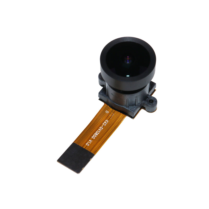
Compare interfaces, resolution and field of view, then discuss optics, mechanics and image tuning.
9 configurations
DVP/MIPI Dual-Lens Recognition Camera

MIPI Dash Cam Camera

Indoor Surveillance Camera

MIPI Dual-Lens Camera

MIPI Camera

Compact MIPI Camera

Action Camera Module

Dual-Lens Depth Camera

Drone Zoom Camera
No matching configurations
Configurations are identified by chipset. — means not specified in the profile. Confirm the FOV axis, lens options and output mode during selection.
MIPI CSI-2 carries camera image data. Integration still requires agreement on the physical interface, lane configuration and data formats used by the host and module. The connector pin count does not describe these details.
Choose one defined capture mode as the starting point. Record power-up, device detection, image output and parameter control before adding modes. Original logs and image files give a clearer debugging record than a description such as “image available” or “black screen.”
Agree who owns the module, adapter board, driver integration, image debugging and application changes. For NVIDIA-based projects, include the carrier board and JetPack / Jetson Linux versions as well as the compute module.