

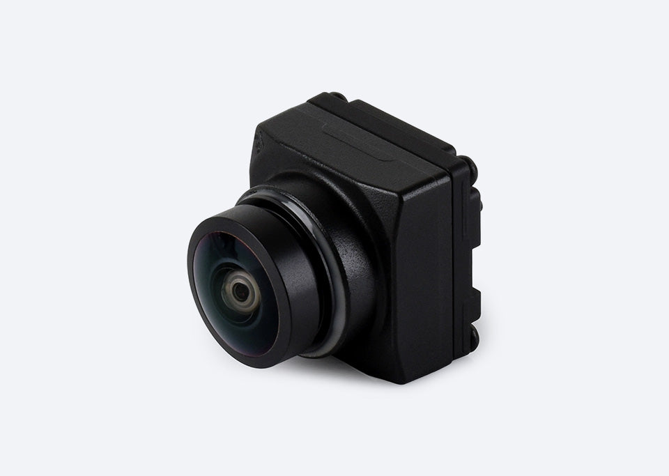
GMSL camera modules
For projects with cameras mounted away from the host. Review the link devices, cabling, power arrangement and camera connections.
- Serializer and deserializer
- Cables and connectors
- Host integration and synchronization
Optics, custom hardware, platform integration and manufacturing checks for automotive, robotics and industrial equipment.

Optical structure illustration
Founded in April 2011, RAWPIC focuses on camera modules and custom development for automotive, robotics and industrial vision, with hardware customization, ISP tuning and camera intrinsic calibration.

Start with the interface to find the imaging approach for your equipment.
For projects with cameras mounted away from the host. Review the link devices, cabling, power arrangement and camera connections.
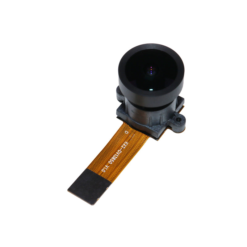
For embedded board integration. Review pin assignments, the CSI interface, available space and sensor driver requirements.

Define the baseline, field of view and synchronization for two-camera capture, along with responsibilities for calibration and processing.
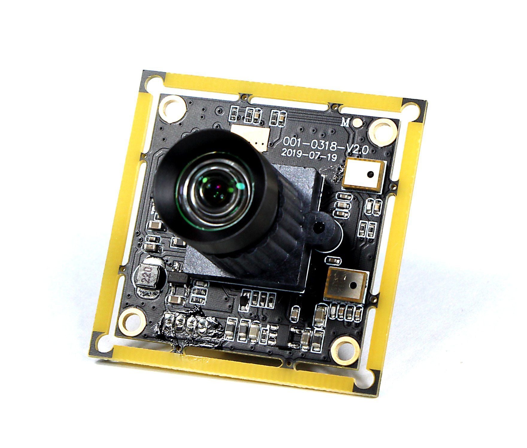
Use the lighting and motion in your application to define the lens, exposure, gain and image evaluation conditions.
Explore precision operations and imaging inspection for camera modules, alongside robotics vision applications.
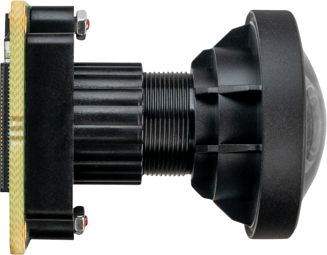
Hardware customization, ISP tuning and camera intrinsic calibration, developed around your module, image quality and imaging geometry requirements.
Define the hardware scope around the lens, board layout, connectors and available installation space.
Set image quality goals and tuning requirements for the target platform and operating conditions.
Calibrate focal length, principal point and lens distortion for the selected lens and imaging configuration.
Imaging task, platform, installation space and schedule.
Candidate approach, responsibilities and acceptance criteria.
Record configurations, image samples and issues.
Review changes, documentation and production requirements.
From vehicle perception to robot navigation and industrial inspection, imaging conditions guide module selection.

Start with the mounting position and imaging task, then define the field of view, cable route, vehicle power interface and environmental validation.
Learn more
Plan image input, synchronization and data handling around the compute platform, robot motion and camera layout.
Learn more
Turn the target, working distance and operating cycle into repeatable imaging tests.
Learn moreDefine the host and data link before specifying the module. Two connection paths address different installation and integration needs.
Read the interface selection guideModule → Serializer → Cable → Deserializer → Host
Module → FPC / Connector → Host CSI interface

Record link devices, connectors, power and platform details before choosing an interface.
Read the guidePrepare hardware revisions, software images and reproducible logs for debugging.
Read the guide
Record distance, lighting, motion and exposure before evaluating application suitability.
Read the guideIn no particular order



















Share the model, interface or platform details you already have. If the project is still at concept stage, describe the equipment, the subject and the problem you need to solve.